

EVPN Multihoming on Catalyst 9000: Port-Channels from Two Independent Switches
vPC on Catalyst switches? Not exactly, but close
Anyone who has designed a Nexus data centre knows the shape of vPC. Two switches, one logical EtherChannel downstream, both links forwarding, and a downstream device with no idea it is talking to two separate chassis.
From IOS-XE 17.18.2, a pair of Catalyst 9000 switches can present the same thing. Their local physical connections bind into a single logical EtherChannel towards a downstream device, in access or trunk mode, and that device (an access switch, a firewall, a WLC, a server) sees one port-channel and behaves accordingly. Cisco calls it EVPN multihoming.
Not exactly vPC, though. The control plane is BGP rather than a proprietary peer protocol, the link between the two switches is routed rather than bridged, and loop prevention works on an entirely different principle. Roughly half of vPC experience transfers directly. The other half is where the differences start to matter, and that is where this article spends its time.
One other reading is worth ruling out first. When Catalyst switches, VXLAN and BGP EVPN appear in the same sentence, most engineers reach for the fabric mental model: overlays, VNIs, a Control Plane node, Catalyst Center pushing intent. This is not that. Cisco calls the deployment model a non-fabric network, which is a clumsy name for something quite specific: the existing Layer 2 or Layer 3 campus retained unchanged in the upstream core, with the distribution pair rebuilt on a standards-based control plane.
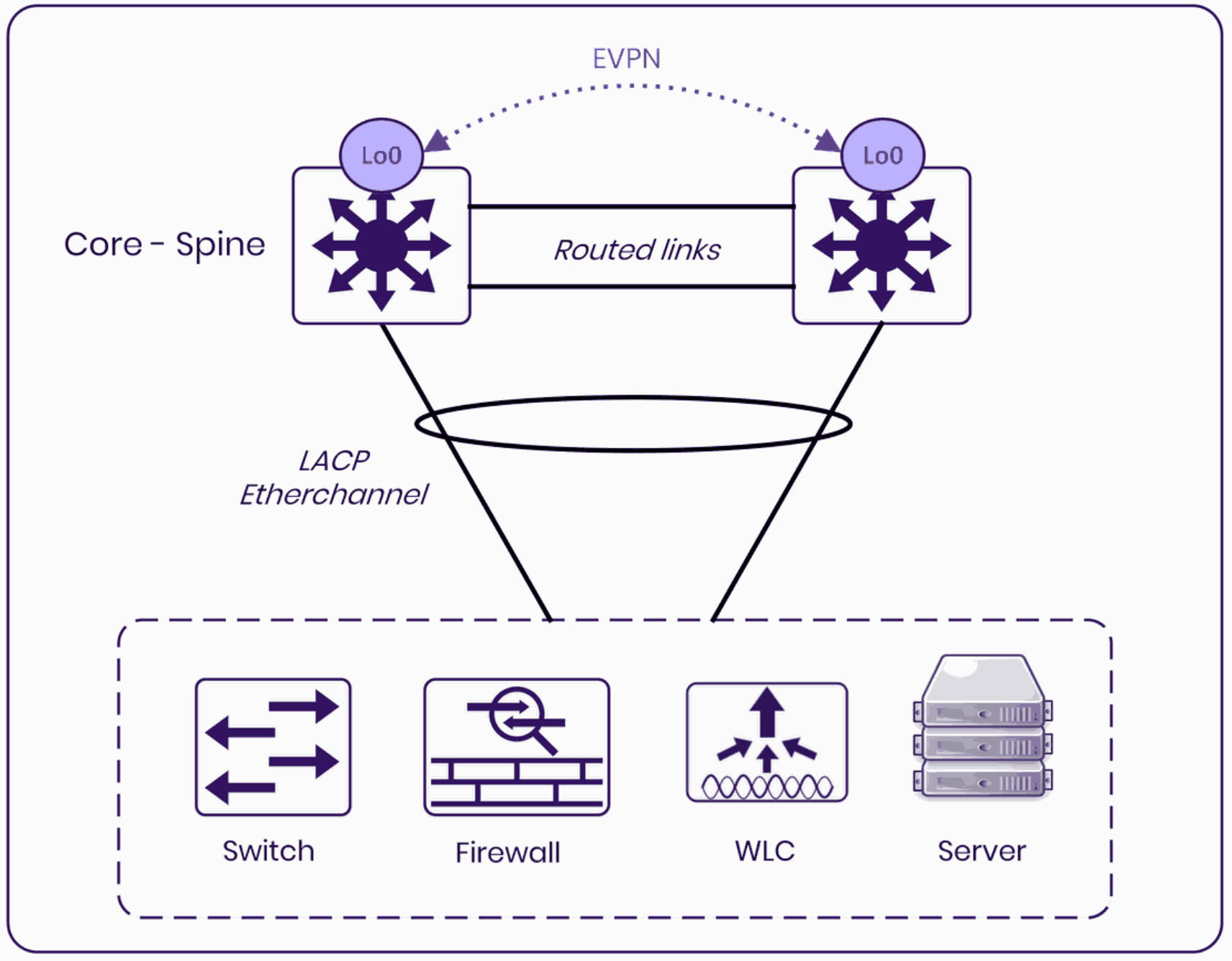
The shape of an EVPN multihomed pair. The EVPN control plane runs between loopbacks, the inter-switch link is routed rather than bridged, and every downstream device sees a single LACP EtherChannel regardless of which physical uplink it is using.
Why EVPN multihoming exists
The devices that need a port-channel from the distribution layer are the ones that have always been awkward. An access switch that is not part of a stack. A wireless LAN controller. A route-mode firewall pair. A server or host that supports link bundling and expects both uplinks to be active. Cisco's list of supported downstream clients covers exactly those, plus anything else that follows standard Layer 2 link bundling.
The problem being solved is equally familiar. Cisco frames it as the accumulated cost of legacy Layer 2 protocols in the campus: spanning tree producing inefficient topologies, traditional Layer 2 designs capping usable switching capacity, and fault detection that is difficult to make deterministic for mission-critical applications.
Every one of those already has a workaround in most campus networks today. That is the point. EVPN multihoming is not solving a new problem, it is replacing a stack of workarounds with a control plane.
What is familiar from vPC
The downstream device needs no special configuration: standard IEEE 802.3ad LACP, or static bundling on both ends where the device cannot run LACP.
Gateway redundancy is handled by an anycast gateway rather than a first-hop redundancy protocol. The anycast-gateway mac auto command, placed in the global l2vpn evpn configuration block, automatically assigns the fixed shared MAC address 0000.5e00.0101 (the VRRP virtual router MAC for virtual router 1) across both switches. The SVI carries an identical IP address on each. Both switches act as the gateway simultaneously for every VLAN. That mutual exclusivity with FHRP is enforced: an anycast gateway SVI with any first-hop redundancy protocol is not supported.
There is an inter-chassis connection between the pair, and there is a mechanism that error-disables the downstream links when a switch loses its connectivity to the core. Single-homed devices continue to work alongside the multihomed ones without any change to their configuration.
That is where the resemblance ends.
The inter-chassis link is Layer 3
This is the adjustment that trips people up, and it is the one worth internalising first. The recommended inter-chassis connection is a routed port-channel with a point-to-point IP address: no switchport, an IPv4 address, and an IGP adjacency. It is not a peer-link in the vPC sense. It carries no native VLANs and it is not what keeps the two switches consistent with each other. BUM replication traffic and VXLAN repair path traffic do transit this link as VXLAN-encapsulated unicast when it is the preferred underlay route between the two VTEPs.
The consequence follows directly from that design. Because the inter-ES path is an IP path, the pair does not depend on it existing. The iBGP session that carries the EVPN control plane is sourced from loopbacks and can reroute over any available Layer 3 path, including the IP core. The direct EtherChannel is preferred because it typically offers the lowest IGP metric to the peer loopback. Cisco's documented recommendation is to size that bundle to match the overall forwarding bandwidth of the ES switch uplinks, because it is the data-plane repair path for traffic that was flowing locally when a member port fails.
The control plane is BGP, and it is standard
EVPN multihoming is built on RFC 7432 and RFC 8365, using the L2VPN EVPN address family over an iBGP session between the two switches. Both switches run the same BGP AS number; the iBGP session is sourced from loopbacks and the iBGP peering over a loopback is required for the L2VPN address family to function. BGP-based Designated Forwarder election and split-horizon filtering replace STP's loop-prevention role on the multihomed Ethernet segment. STP may remain operational elsewhere in the campus for single-homed and non-EVPN connected devices. Route Type 4 advertises the Ethernet Segment Identifier and drives auto-discovery and Designated Forwarder election. Route Type 1 is defined in RFC 7432 to handle split-horizon filtering, aliasing (load balancing across multiple PEs in a multi-hop fabric) and fast convergence with mass MAC withdrawal on link failure. In this non-fabric deployment, aliasing is explicitly disabled via multihoming aliasing disable: with only two directly peered switches there are no remote PEs for aliasing to distribute load across, so the mechanism serves no purpose here. The RT-1 functions that remain active are split-horizon filtering and mass MAC withdrawal on link failure.
The Ethernet Segment Identifier is the 10-byte value that ties the two switches together for a given downstream connection. With LACP it is auto-derived using evpn ethernet-segment auto lacp df-election wait-time 1. Without LACP it is assigned manually as a Type 0 nine-octet value or a Type 3 system-MAC value, with redundancy mode all-active set explicitly. The scope is per port-channel, not per pair, which is a different granularity from a vPC domain: one redundancy group of two switches supports up to 48 ES port-channel interfaces, each independently discovered and elected.
Four commands appear in every reference configuration under the l2vpn evpn block, and each does something distinct. multihoming aliasing disable turns off per-EVI aliasing advertisements: aliasing is used in multi-hop EVPN fabrics to distribute load across multiple PEs, and with only two directly peered switches there are no remote PEs for it to serve. advertise mac disable disables automatic per-EVI EVPN route-type generation, which is equally unnecessary in this two-switch scope. multicast advertise sync-only enables IGMP/MLD join and leaf state synchronisation between the pair, keeping multicast group and receiver state consistent across both switches. multihoming peering adjacent configures direct iBGP EVPN peering for the non-fabric context, scoping the peering relationship to the adjacent switch rather than a wider fabric topology.
Blocking is replaced by Designated Forwarder election
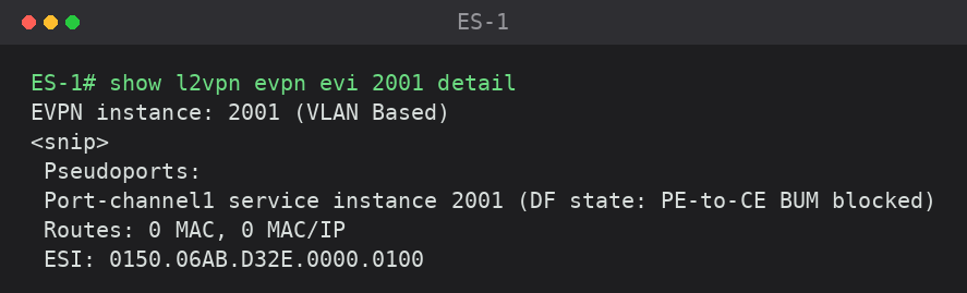
In an STP network, loop prevention means blocking a link for all traffic. EVPN multihoming decouples the traffic types instead. On a per-ES-port and per-VLAN basis, one switch is elected Designated Forwarder and forwards BUM traffic. The peer becomes non-DF and blocks BUM on the shared ES EtherChannel. Unicast traffic remains all-active on both. The election is derived from an internal modulo hash, which spreads DF duties across the pair rather than concentrating them on one switch.
Both sides of the election are visible on the pair. The following outputs are reproduced from Cisco's IOS XE 17.18.x configuration guide verification examples. On ES-1:
And on ES-2:
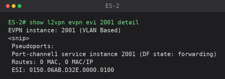
Same ESI on both, opposite roles for EVI 2001. On a different VLAN, or on a different Ethernet Segment, the roles may well be reversed. The hash deliberately distributes the DF load rather than electing one switch as the primary for everything.
BUM replication between the pair uses ingress replication, configured with replication-type ingress in the l2vpn evpn block: unicast VXLAN to the peer VTEP, with no dependency on underlay multicast. This is worth contrasting with L2 Flooding in SD-Access, where enabling flooding creates a dependency on Any Source Multicast in the underlay, with all the Anycast RP and MSDP design that implies. We covered that infrastructure in detail in our earlier article on Anycast RP for SD-Access. Here, because there is only ever one peer to replicate to, underlay multicast is not required at all.
Recovery uses a VXLAN tunnel, not flooding
MAC, IPv4 and IPv6 host addresses are synchronised between the two switches over the BGP control plane in real time. The inter-ES Layer 2 VXLAN tunnel is pre-programmed rather than built on demand. When a local ES member port fails, traffic for hosts that were reached via that port is rerouted over the pre-programmed tunnel to the peer without any data-plane flooding to relearn addresses.
The following output is reproduced from Cisco's IOS XE 17.18.x configuration guide verification examples. On ES1:
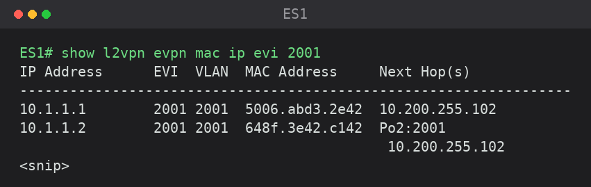
The second host is reachable two ways: locally via Po2, and via the peer loopback. The local path is preferred under normal conditions, and the tunnel is already programmed as the fallback rather than being established at the moment of failure. The first host has no local path and is only reachable through the peer, demonstrating the synchronisation working correctly in the other direction.
This is a proactive control-plane model rather than a reactive learning one. The same principle appeared in our article on SD-Access wireless roaming, where we described how LISP-based host tracking avoids the flooding-on-move behaviour of traditional MAC learning. Here it applies to a much smaller scope, two distribution switches rather than a full fabric, but the design intention is identical.
The two switches stay independent
Each ES switch maintains its own control, management and data plane. Cisco explicitly permits a pair with different platform types, different modules and different IOS-XE versions, describing it as no different from running OSPF or BGP between two separate boxes. The recommendation is still to run a common platform and version for consistent behaviour, but the architecture does not require it. That said, for a controlled-availability feature, the caveats matter in practice: feature intersection between platforms may vary across releases, defect scope can differ, and upgrade order and interoperability should be validated before deployment. TAC engagement is the documented support model for this feature, and for heterogeneous pairs in particular it is worth raising platform and release combinations with Cisco before committing to a design.
This independence is the point. It is also where the comparison with StackWise Virtual becomes concrete.
Why it matters that this is Catalyst
Campus distribution has had two common approaches for dual-homing an access switch: a first-hop redundancy protocol with spanning tree accepting a blocked uplink, or StackWise Virtual to present the pair as one logical switch. The second option delivers the port-channel, at the cost of a shared control plane and shared upgrade fate.
EVPN multihoming decouples those two things. The downstream port-channel is available without merging the two switches into one logical system, and the upgrade paths stay separate. On Catalyst 9400 and 9600 with redundant supervisors, ISSU is intra-chassis — the switch being upgraded keeps forwarding via NSF/SSO, and the EVPN control plane and the multihomed network remain operational across both switches during the upgrade. Catalyst 9500 High Performance, as a fixed standalone platform, still requires a reboot cycle. Capacity drops temporarily; availability does not, provided the platform supports ISSU.
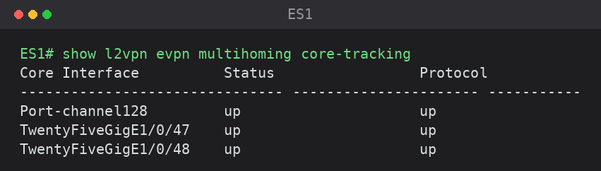
Core isolation is handled explicitly rather than inferred. The evpn multihoming core-tracking command is applied per Layer 3 interface on both the inter-ES port-channel and the core uplinks. If a switch loses every tracked Layer 3 path and the iBGP session to its peer, it error-disables its local ES ports, steering the upstream data plane to an alternate functioning ES switch. When any tracked path recovers and iBGP re-establishes, the ports are recovered automatically.
The following output is reproduced from Cisco's IOS XE 17.18.x configuration guide verification examples.
The trade-offs
The scale figures are modest and should shape the design from the start. Two ES switches per redundancy group, 48 ES port-channel interfaces, 200 VLANs, 10,000 MAC addresses, 10,000 IPv4 and 20,000 IPv6 addresses per system. These are campus distribution numbers, not data centre numbers, and the VLAN ceiling in particular is worth checking against the existing distribution block before anything else.
The platform restrictions will end the conversation early for some deployments. EVPN multihoming is not supported on Catalyst 9500-X, Catalyst 9600-Sup2, C9350 Smart Switches or C9610 Smart Switches. It cannot be combined with StackWise Virtual on the same switch for Catalyst 9400, 9500-H or 9600, which makes the two approaches to distribution redundancy mutually exclusive per device.
Several Layer 2 protocols and topologies are excluded. PAgP is not supported on an ES-enabled EtherChannel. REP is not supported on a Layer 2 ES port. A Layer 2 ring physical topology connecting into EVPN multihoming is not supported at all. An IPv6-only underlay is also excluded, which matters if you have been moving that direction in the core.
Routing over an EVPN multihoming ES EtherChannel is limited to eBGP and static routing. Cisco's documented firewall example uses SVI-based eBGP, with the VLAN trunked over the ES EtherChannel rather than configuring the ES port-channel itself as a routed interface. No OSPF, no EIGRP, no other dynamic protocol. This restriction deserves more attention than its position in the documentation suggests, because dual-homing a route-mode firewall pair is one of the more attractive use cases and firewall pairs commonly peer with the distribution layer over an IGP today. If yours does, adopting EVPN multihoming is a routing design change rather than a migration, and it needs to be costed as one.
Underlay links between VTEPs must accommodate VXLAN encapsulation overhead — VXLAN adds 50 bytes per frame — so jumbo frames are typically required on those paths.
Upgrade paths need checking before planning a rollout. ISSU from a release earlier than IOS-XE 17.18.2 is not supported on Catalyst 9400 and 9600 modular platforms with redundant supervisors.
There is also one line in the documentation to raise with any customer before this reaches a design document. Cisco states that "EVPN multihoming in fabric and non-fabric networks is a controlled availability feature with Cisco Technical Assistance Center support for issues," and repeats it twice in the same chapter. That is a deliberate signal about deployment maturity. It belongs in the risk conversation at the start of a project, not in a caveat at the end of a design document.
Our experience
At Entek IT, our testing with EVPN multihoming has been in the lab so far, and this article reflects the Cisco design documentation and those early results rather than a production deployment. That distinction matters given the controlled availability status. At this stage the useful work is understanding the mechanism and its constraints, not scheduling a migration.
What is already clear is that EVPN multihoming moves campus distribution from a platform feature to a routing design. There is an IGP and an iBGP session between two distribution switches, an inter-chassis bundle sized as a data-plane repair path, core interfaces tracked deliberately, and DF election to reason about per VLAN. Enabling multihoming on a port-channel is a handful of configuration lines. Building the Layer 3 design underneath it so that it fails predictably is an engineering task, and the separation between those two things is not obvious from the feature overview.
This is the same gap we described when writing about L2 Flooding in SD-Access. The feature is straightforward to enable, and the infrastructure it quietly depends on is where deployments succeed or fail. The difference here is that the infrastructure is not hidden behind Catalyst Center's provisioning model. It is just less visible than the port-channel it creates.
The next case in our lab is one this article has deliberately left brief. We are connecting a Cisco Secure Firewall to a Catalyst 9000 pair over an ES EtherChannel with EVPN multihoming underneath, and documenting the end-to-end behaviour. The eBGP and static routing restriction described above is precisely the constraint that shapes that design, and it deserves its own deep dive rather than a paragraph here. Combined with the identity-based policy work we covered in our earlier article on extending identity-based policies to Cisco Firepower, it builds a more complete picture of how a firewall pair actually attaches to a multihomed distribution layer. That will follow as a separate piece.
If you are weighing EVPN multihoming against StackWise Virtual for a distribution refresh, or working through how a dual-homed firewall pair fits into it, reach out to our team at Entek IT. We are happy to work through the design with you while it is still a drawing rather than a change window.
Related articles: Anycast RP for SD-Access: Supporting L2 Flooding with Underlay Multicast | SD-Access LISP Wireless Roaming | Security Service Insertion in Cisco SD-Access