


This is not a new segmentation feature
Before we go any further, let us rule out the most common misreading of this topic. Nothing about your segmentation model changes here. Your SGTs are the same SGTs. Your matrix is the same matrix. The authorisation policy that assigns a tag to an endpoint session is untouched, and the enforcement behaviour of an SGACL on an access switch is identical.
What changes is the transport. Specifically, how a Catalyst switch asks Cisco ISE for the environment data and the SGACL policies it needs in order to enforce group-based policy, and how ISE answers. That conversation used to ride RADIUS over UDP. From IOS XE Amsterdam 17.1.1 (with ISE 2.7 or later on the policy server side), REST over HTTPS is the default mode for new TrustSec policy distribution configurations. Devices with an existing cts authorization list configuration continue to use RADIUS until that configuration is removed and REST mode is explicitly enabled.
That distinction matters, because a change of transport is not a cosmetic change. It moves a control-plane dependency from a protocol your team has run for fifteen years onto a protocol with a certificate lifecycle, a TCP port that has to be open end to end, and a failover model that behaves nothing like RADIUS server groups. This article is about that mechanism, and about the design consequences that follow from it.
Why RADIUS was the wrong carrier for this traffic
RADIUS is an excellent protocol for what it was designed to do: carry a small, transactional authentication exchange between a network access device and a policy server. TrustSec asked it to do something else. Environment data downloads, the SG-Name table and SGACL policy content are bulk, structured data. RADIUS carries them as attribute-value pairs over UDP, with the classic consequences: application-layer retransmission and duplicate detection over UDP with datagram-size limits that become problematic as the SG-Name table and SGACL content grow, and a device-authentication model with its own operational pain. In the NDAC device-authentication path, a Protected Access Credential (PAC) is provisioned via EAP-FAST — a source of operational pain distinct from the environment data and SGACL download path itself. Anyone who has spent an afternoon on an OOB TrustSec PAC screen in ISE, generating and re-generating a PAC for a switch that will not complete NDAC authentication, knows exactly the failure mode we are describing.
Cisco's own framing in the IOS XE TrustSec configuration guide is direct about this. The REST-based protocol is described as more secure, more reliable and faster for SGACL policy and environment data provisioning than the older RADIUS-based method. In practice, the reliability claim is the interesting one. You are swapping a datagram protocol carrying structured policy for JSON over TLS on top of TCP, and getting flow control, ordering and retransmission from the transport layer instead of building it into the application.
Both methods remain supported, but only one can be active on a device at a time. The device is in REST mode by default, and configuring cts authorization list moves it back to RADIUS. The two configuration models are mutually exclusive, and IOS XE tells you so if you try to mix them:

This is worth internalising early, because it defines your migration unit. There is no partial migration in which environment data comes over HTTPS while SGACL policy still comes over RADIUS. It is a per-device cutover, all or nothing.
What actually happens on the wire
The message flow between the switch and ISE is documented in detail, and it is worth walking through because several of the design constraints fall directly out of it.
Cisco ISE runs its REST API service for this purpose on a TLS 1.2 socket on TCP port 9063, and that port is fixed. The IOS XE documentation is explicit that only port 9063 is supported as the ERS server port. There is a port command in the policy-server submode, but the command note states that the ERS server port number must be 9063 and cannot be changed. We will come back to a documentation inconsistency on this point, because the configuration examples in the same guide disagree with it.
The switch initiates a TCP connection to ISE. ISE only accepts ingress connections from devices whose IP address is configured in the ISE network device definition. Connection requests from a source IP that ISE does not recognise are dropped, and an audit log entry is created. That is a useful troubleshooting signal, and it is also a design constraint: the source IP that the switch uses for its HTTP client has to match what ISE has on record, which is why ip http client source-interface is a prerequisite rather than a nicety.
The TLS handshake requires the switch to trust the ISE server certificate. Only the fingerprint or signature of the server certificate needs to be exported and installed on the device under a trustpoint. The private key of the server certificate is not imported. In IOS XE 17.18.x, third-party CA certificates and certificate chains are supported. That was not always the case: in the original 17.1.1 implementation only self-signed certificates were supported, so if you are reading older lab notes, check the release they were written against.
After the TLS session is up, the HTTP client on the switch makes its REST calls. The connection model is what Cisco calls "make or break": there is no persistent TLS session between the switch and ISE. Once a connection is established the device can submit multiple REST calls over it, and when all requests have been processed the server closes the connection with a TCP FIN. A new set of calls means a new connection and a new handshake.
Every REST call carries username and password authentication. Those credentials are not arbitrary. The device ID and password configured in the ISE network device definition are what the switch presents as its REST username and password, which is why the ISE-side network device configuration has to be updated before any of this works.
Environment data: what the switch asks for, and what it gets back
The environment data request from the switch to ISE is small. It carries the device name and the device capability.
The response is where the useful content sits:
- Device SGT. The security group tag of the switch itself, derived by ISE from the device name.
- Server list. The list of Cisco TrustSec servers configured in ISE.
- SG-Name table. The mapping between numeric SGT values and their names.
- Refresh time. When the environment data will next be refreshed.
There is a behaviour on refresh that catches people out. As part of an environment data refresh, the previously received servers are deleted and the newly received servers are added to the list. As a result of that refresh, the server list statistics restart from zero, the server status is set to Inactive and the IP address state is set to Reachable. The device then rebuilds statistics and status from subsequent policy requests and responses.
If you are polling show cts policy-server statistics into a monitoring system and alerting on counters, this matters. Your counters are not monotonic. They reset on every environment data refresh, and the documentation separately confirms that server statistics are not persistent after a refresh. Build your monitoring accordingly.
The private server list, and why it matters more than your configuration
This is the part of the design we would highlight to any team planning a rollout, because it inverts the usual assumption that the servers a switch talks to are the servers you configured on the switch.
There are two server lists:
- The public list is what you configure under
cts policy-server name. This is your bootstrap. - The private list is what ISE returns inside the environment data. These are the servers the device will actually use.
The sequence is straightforward once you see it. On first boot the device selects a server from the public list. If cts environment-data enable is configured, it uses that public server to download the private server list from ISE. After the private list is successfully received, all subsequent requests use the private list. The public list becomes a fallback that is only consulted if every server in the private list is dead.
The operational implication is significant. Your firewall policy, your VRF reachability and your routing all have to accommodate a list of ISE nodes that the switch learns dynamically from ISE, not the one or two addresses you typed into the configuration. Add a PSN to the TrustSec HTTPS server list in ISE and affected devices will learn the new entry on their next environment data refresh. Depending on their server selection mode, they may begin attempting to reach it on TCP/9063. If the firewall rule was written against the two addresses in the switch configuration, that new PSN is unreachable, and you will discover it as a policy download failure rather than as a routing alarm.
This is also where a vendor GUI hides real complexity. Selecting which ISE nodes serve TrustSec data over HTTPS is a selection screen. Making those nodes reachable on TCP/9063 from the HTTP client source interface of every access switch, through every firewall and every VRF boundary in the estate, is an engineering task with a change window attached.
Server selection and failover
Within each list, the device has two selection modes.
In-order selection is the default. Servers are picked in the order in which they were configured (public list) or downloaded (private list). Once a server is selected the device stays on it until it is marked dead, then moves to the next.
Random server selection exists because in-order selection has an obvious failure mode at scale: if every switch always picks the first configured server, one ISE node absorbs the entire estate. With cts policy-server order random, each device generates a random number and selects a server as:

The random number generator is seeded from the unique board ID and the Cisco TrustSec process ID of the device, so that different devices genuinely produce different numbers rather than all converging on the same value. Dead servers are excluded from the count when a new server is picked. Once selected, all future requests go to that server until it is marked dead.
For any deployment above a handful of switches, we would treat cts policy-server order random as the default rather than the exception. In-order selection concentrates load on the first configured server. At scale, this means a large fraction of the estate may select the same PSN — a capacity risk that becomes visible when a policy refresh event drives simultaneous requests. Validate server distribution and refresh timing before relying on in-order selection in a large deployment.
The order of selection across lists is private first, then public. From Cisco IOS XE 17.2.1, multiple IPv4 and IPv6 addresses per server are supported, with up to 8 IPv4 and 8 IPv6 addresses per server, and the IP selection order within a server is IPv4 first, then IPv6, then FQDN. Only one FQDN per server is supported.
There is also explicit overload handling. The TrustSec device honours an HTTP 429 response from ISE, which ISE sends when it is overloaded. On receiving a 429 for a particular server, the device marks that server dead and switches to the next server in the list. The next retry attempt for that server happens after 60 seconds. A failed IP address and server combination carries the same 60-second penalty before the device tries the next combination.
Liveliness, or rather the absence of it
This is the single most important behavioural difference from RADIUS, and it deserves its own section.
There is no liveliness detection phase. Cisco states it plainly: whether a server is alive is determined only after sending an environment data or SGACL request to ISE, and there is no liveliness detection after a server is configured or downloaded as part of a server list. The default status for all server types is alive.
So the device does not probe. It discovers a dead server by failing to get a response to a real policy request. A server can be marked dead for any of the following reasons:
- The configured IP address is not reachable.
- Incorrect port number.
- The ISE instance with that IP address is down.
- The interface towards ISE is down.
- A TLS handshake failure.
- An HTTP response timeout.
- An incorrectly configured domain name, where a domain name is used.
If a server has both a static IP address and a domain name configured, the static IP takes preference. If there is no response on the static IP, the device tries the domain name. Only when both fail is the server marked dead.
When every server in both the private and public lists is dead, the recovery mechanism is trigger-driven rather than timer-driven: the device waits for the next TrustSec request (a policy refresh, an environment data download or refresh, and so on), and at that point marks all servers alive again to retry. If there is no trigger for a new TrustSec request, the servers simply remain in the dead state.
Read that last sentence again, because it is the operational trap. A switch can sit with every policy server marked dead and generate no further attempts until something triggers a new TrustSec request. Your monitoring needs to look at show cts policy-server statistics, not at whether the switch is actively complaining.
One further nuance for redundant platforms: SGACL and environment data are synchronised from the active to the standby device after the policy is installed, but REST API connections and sessions are not synchronised during a switchover. Policy survives a switchover. The transport state does not.
Configuring it on IOS XE 17.18.x
The configuration is short, which is precisely why it is worth explaining rather than listing. The following snippets are the documented examples from the Cisco TrustSec Configuration Guide for IOS XE 17.18.x (Catalyst 9300), with our commentary.
The trustpoint first, because without it the TLS handshake fails and everything downstream fails with it:

The REST credentials, which must already exist in ISE as the REST API access credentials before you configure them here:

The policy server definition itself, plus the enforcement statement that has to be in place before policy can be downloaded:

The default timeout is 5 seconds and the default retransmit count is 4. JSON is the default content type whether or not content-type json is present. The port subcommand accepts only 9063; it is shown here for completeness.
And finally the environment data configuration, which needs the device ID to match the name used to add the network access device in ISE:

Plus the prerequisite that is easy to overlook because it lives outside the cts configuration entirely:

Three inconsistencies in the guide's sample configuration are worth flagging. The policy download example in the configuration chapter shows port 2010, which directly contradicts the restriction that only port 9063 is supported as the ERS server port. The username example omits the password keyword that the command syntax requires. And the environment data example uses cts env-data enable where the procedural steps use cts environment-data enable. Follow the command procedures and the command reference, not the copy-paste sample blocks.
If you are running VRFs, note that from Cisco IOS XE Bengaluru 17.4.1 the RADIUS automated tester can be made VRF-aware using the vrf keyword with the automate-tester command, which requires the global ipv4/ipv6 source interface <interface> vrf <vrf-name> configuration. Without that, the RADIUS Automated Testing feature is not supported in a VRF environment.
ISE-side configuration
Four steps on the ISE side complete the picture.
First, on each network device, enable HTTP file transfer and require credentials. Second, in ISE go to Work Centers > TrustSec > Settings > General TrustSec Settings and enable "Trustsec REST API Service for Network Devices" (the checkbox is labelled "Enable HTTP Service" and its description reads "Use HTTP to transfer TrustSec data to network devices over port 9063"). Third, edit each PSN's network device definition, check "Enable HTTP REST API" and enter the device HTTP credentials. Fourth, go to Work Centers > TrustSec > Components > Trustsec Servers > HTTPS Servers and add each TrustSec NAD as a TrustSec HTTPS Server.
One constraint here is worth its own sentence. If you configure only one node for HTTPS, the TrustSec servers that are not configured for HTTPS do not appear in the TrustSec server list. You must configure all TrustSec-enabled nodes in your deployment for HTTPS. If no PSNs are configured for HTTPS, then RADIUS is used. This is an all-or-nothing switch per PSN, not a gradual migration path.
ISE also supports adding external servers (such as a load balancer) to the HTTPS Servers list. Two modes exist: SSL Termination, in which the load balancer terminates TLS and must have its own certificate trusted by the NADs; and SSL Passthrough, in which the load balancer translates IP only, the NAD trusts the PSN certificate directly, and the PSN certificate must include the external server IP as a Subject Alternative Name. Either mode requires connection persistence to a single PSN.
ISE requires Advantage licensing for TrustSec. The Advantage tier explicitly includes "Security Group Tagging, Cisco ACI integration, TrustSec." It is not available under Essentials. The REST transport itself does not carry a separate device licence beyond the ISE Advantage entitlement.
Verifying it
Three commands do most of the work. The following outputs are the documented examples from the Cisco configuration guide rather than our own lab captures.
show cts policy-server details name confirms what the device thinks it is talking to, including whether the trustpoint and content type resolved as expected:

show cts policy-server statistics active is the one to instrument. It breaks failures down by HTTP status code, which turns "TrustSec is not working" into a specific diagnosis. A run of 401 responses is a credentials problem. A run of 403 is authorisation. TLS handshake errors point at the trustpoint or the certificate chain. Repeated 503 responses point at ISE capacity rather than at your switch. A 429 (ISE overload) response has no dedicated counter in this output; it increments HTTP Other Error rather than appearing by name:

show cts server-list shows the private list, which is to say the servers the device is actually using rather than the ones you configured:
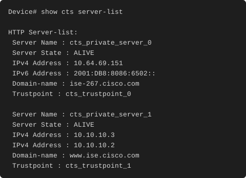
Note the trustpoint names in that output. The private server entries carry their own trustpoints, learned as part of the server list, rather than the one you configured under the policy server definition. When you are debugging a TLS failure against a private-list server, that is where to look.
For deeper work there are two debugs: debug cts policy-server http for the HTTP client, and debug cts policy-server json for the JSON client. On the ISE side, enabling ERS debug logs all ERS traffic. Cisco's own documentation warns not to leave ERS debug enabled for more than 30 minutes because of the log volume it produces.
What has not moved: CoA still rides RADIUS
This is the point that most changes how you should think about the migration. TrustSec Change of Authorisation still uses RADIUS as its protocol. Cisco states this both as a restriction and as a note in the overview.
So the picture after migration is hybrid, not RADIUS-free. When ISE policy changes, ISE sends a RADIUS CoA to the device, which then pulls the updated SGACL policy over HTTPS. Environment data is refreshed separately on a time-based schedule. Both mechanisms remain in the design after migration: RADIUS for CoA notification and HTTPS for the subsequent data pull. Your RADIUS shared secrets, your CoA port and your UDP reachability all remain in the design. What you have removed is the bulk data transfer, not the notification channel.
We mention this specifically because we have seen the migration mis-scoped on the assumption that HTTPS replaces RADIUS for TrustSec entirely. It does not. It replaces the download, and it adds a second dependency alongside the one you already had.
It is also worth noting that, in the NX-OS releases reviewed for this article, neither platform supports the REST/HTTPS cts policy-server transport. The Nexus 7000 (NX-OS 8.x) and Nexus 9000 (NX-OS 9.3x) TrustSec configuration guides contain no mention of cts policy-server, TCP/9063 or HTTPS-based policy download. Later NX-OS releases were not checked. If you have NX-OS devices in your TrustSec estate, check the relevant release documentation, but on the releases confirmed here they remain on the RADIUS-based model.
Trade-offs worth designing around
Pulling the above together, these are the design points we would raise in a review:
- PKI becomes a policy dependency. A certificate that expires on an ISE node no longer just inconveniences administrators logging into the GUI. It breaks the TLS handshake, marks the server dead and stops policy download on every switch that selected it. Certificate lifecycle management moves from an administrative task to a segmentation availability task.
- Firewall policy tracks a list you do not directly control. The private server list comes from ISE. Adding or renumbering a PSN changes what your switches try to reach on TCP/9063.
- Failover is reactive, not proactive. No probing, 60-second penalties on a failed server and IP combination, and a recovery path that only runs when something triggers a new TrustSec request.
- Statistics are not durable. They reset on every environment data refresh, which shapes how you monitor.
- Migration is a per-device cutover.
cts environment-data enableandcts authorization listare mutually exclusive, and the device refuses to hold both configurations at once. - Redundancy is partial. Policy synchronises to the standby, REST sessions do not.
- Port 9063 is fixed. There is no scope for moving it to fit an existing firewall policy.
- HTTPS mode is all-or-nothing per PSN on the ISE side. Partial deployment leaves some PSNs invisible to the TrustSec server list.
None of these are reasons to stay on RADIUS. They are reasons to plan the change as an infrastructure project rather than a configuration change. Enabling it on the switch is a dozen lines. Building the certificate trust, the reachability and the operational visibility underneath it is the engineering task.
Where this is heading
The feature history is short but the direction is clear. SGACL and environment data download over REST arrived in Cisco IOS XE Amsterdam 17.1.1, with IPv6 policy server support following in 17.2.1. Third-party CA certificate chain support is documented in IOS XE 17.18.x. The exact release in which the 17.1.1 self-signed-only restriction was lifted is not recorded in Cisco's feature history tables.
From Cisco IOS XE 26.1.1 (with ISE 3.5 or later), ISE pushes the IPv6 addresses of PSNs in addition to their IPv4 addresses as part of environment data. Prior to that release, the server list IPs received in environment data were IPv4 only. That release also introduces round-robin failover for picking an active server when a list contains both IPv4 and IPv6 addresses. The device typically prioritises the server address type that matches its configured source interface address type for SGACL policy download. Mixed-mode (device source IPv4 plus ISE IPv6, or vice versa) is not supported.
For anyone running or planning a dual-stack campus, the 26.1.1 environment data change is the one to track. It removes the last IPv4 assumption from the policy distribution path.
Our Experience
At Entek IT, we have been designing and running identity-based segmentation for customers long enough to have carried TrustSec through several transport generations, and our consistent observation is that the problems in these deployments are rarely in the policy model. They are in the plumbing underneath it.
At multiple customers we have seen the same three issues account for most of the trouble tickets on this feature. The first is certificate trust: a trustpoint built against a self-signed ISE certificate during a proof of concept, then never revisited when the customer moved to an internal CA. The second is firewall policy written against the configured public server list rather than the downloaded private list, which works perfectly until ISE is scaled out and then fails silently on the next environment data refresh. The third is monitoring: nobody is watching show cts policy-server statistics, and a switch sits with all servers marked dead until an unrelated change triggers a new TrustSec request.
Our standard approach now is to treat the trustpoint and the reachability design as first-class deliverables in the low-level design, not as prerequisites buried in an implementation guide. We also default to cts policy-server order random in anything beyond a small site, because the load concentration under in-order selection is genuinely invisible until it is not.
For the wider picture of what happens to tags once they are distributed, we covered the propagation and integration side in our earlier article "Extending Identity Based Policies to Cisco Firepower," and the identity-driven traffic steering work in "New Feature: Security Service Insertion in Cisco SD-Access." This article is the layer underneath both of them: the mechanism that gets the policy onto the switch in the first place.
If you are planning a TrustSec deployment, migrating an existing one off RADIUS-based provisioning, or trying to work out why policy download is failing on a subset of your estate, we are always happy to talk it through. Get in touch with the team at Entek IT.